
Flywing EC-135 XplorerHD Installation
- IQ

- Jul 9
- 3 min read
If you have printed our free .stl mount for the EC-135, here is how we designed it to be installed with the XplorerHD.


Before getting started, you will need 2x extra screws (2mm on the threaded side) and we chose to use tap screws.
You may be able to use regular 2mm width screws but may require tapping the 3D print and the wooden plate. More on this later.
Step 1:
Remove the 2x screws located as shown in the diagram 1. They will be already attached to battery tray.
These screws hold down the landing gear below and reuse these screws so please hold onto them.
Lastly, the washers you see in Diagram 1, we will not be reusing them so you can keep them aside if you want to reassemble to stock settings in the future.

Step 2:
Flip the helicopter upside down and using the 2x screws that you just removed, install them as seen. (Diagram 2)
If you notice on the rear side of the landing gear (not shown in picture but it will be towards the "right" in this orientation) they are screwed in this way so basically copying exactly how it is from the rear and doing the same for these 2 holes.

Step 3:
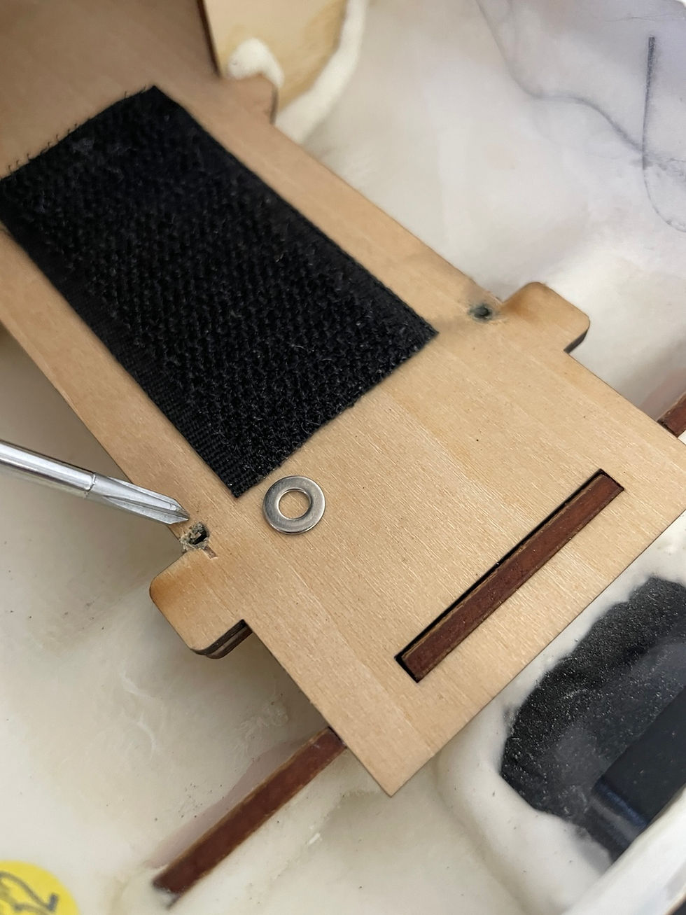
Using the 2x extra screws (which we mentioned at the top of this post), place them as seen on the brackets of the 3D mount.
We created a divot in those locations to help the screws find their way into the hole.
Also, (not shown in picture) the hole on top of the plate allows to move your screw driver directly above the screw. (These holes in the middle of the plate is NOT holes to mount the XplorerHD camera unit)

Step 4:
The slot will be placed towards the rear of the battery compartment and slide into the wooden part as shown in Diagram 4.
Once the 2x screw are tightened down on the post, it should create enough tension so the plate won't slide around.
Note, the amount of adhesive Flywing applies may result in this slot from going further in or not. As long as there is 75% of this lip going down into the slot will be enough.
After installation, it should look like this.
(Note: Your 3D printed bracket is the most up to date and won't look like our prototype as it is missing the 2 access holes in the middle of the print for your screw driver)

Step 5:
Line up the rear 2x holes and the front 2x holes on the XplorerHD sled and the 3D printed mount.
The hardware (screw and nut) are supplied in your kit and you can use those to secure the XplorerHD onto the 3D bracket.
For piece of mind, we also used double sided tape to really secure the camera kit onto the 3D bracket.

Step 6:
Note: If you are using the Flywing battery for this unit, you may need to remove the velcro to the larger side for the battery to fit. (This is not our fault as you will discover it doesn't fit)
We ran the passthrough harness in between the gimbal and VTX. Please make sure the wires don't get caught in the fan!!!

Fully assembled!
NOTE: The range might be affected due the antennas being too close to the rest of helicopter's electronics.
For the test run, please run the helicopter on GPS mode and away from any type of obstacles in case the video might drop out.
Do not exceed 50 ft. and always fly in a open and safe space!


Comments