
Extra Harness?
- IQ

- Jul 14, 2025
- 5 min read
Note: Certain tasks are NOT simple and require some extensive knowledge. Without proper installation may result in permanent damage to the XplorerHD and the hardware used!
Besides our passthrough PnP (Plug and Play) harness that powers on the XplorerHD unit, there is another 8-pin wire harness included in the package. You can get creative with this one but we see it used mostly for flying applications with an "wing" version Flight Controller. You can unlock a few features (but not limited to these below) like:
OSD (On Screen Display) Data directly to your goggles
Manual Gimbal Control (Instead of using the head tracker, you can assign it to a knob (potentiometer)
Create a dedicated PnP plug for your battery choice
Disclaimer: Due to our tech team being very limited in resources, we CANNOT fully support getting these features set up as the UI and hardware are NOT our products and they go through upgrades. However, there are plenty of content online or you can directly contact the respective flight controller and/or UI support groups. Attempting these are strictly your responsibility! We just wanted to share what is possible with the XplorerHD.
Pin out on 8-Pin Harness

From left to right, here is how the pin out is when connected to our XplorerHD sled
RED: Power (7v - 26v) If you are using an R/C that runs higher than 6s, please consider running a separate battery!
Black: Ground
RX
TX
PWM1
PWM2
PWM3
PWM4
Creating a dedicated plug for your battery

The Red (Power) and Black (Ground) wires on this harness is exactly the same as our Power Lead pass through harness. However, if you have a plug for your batteries that uses different connectors (I.e Deans, IC, EC, etc.) You can use the 8-Pin harness to for the connector you wish to use.
You can also make a PnP like our Power Lead harness by acquiring both the male and female for your respective plug.
PLEASE MAKE SURE THE + and - are correct before plugging in the battery!!!
The XplorerHD does NOT have polarity protection and you may burn out the system!
OSD Wiring
You will need an Flight Controller with open an UART (Universal Asynchronous Receiver/Transmitter) to have OSD in your goggles.

Although the XplorerHD current setup can tell you your Video's signal strength, battery voltage, and a finicky range estimation, you can also add more features to tell you more telemetry (data) for your R/C like throttle position, artificial horizon and much more.
However, please note that you may need extra hardware like GPS, Barometer, and Magnetometer for distance, altitude, and position (Lat and Long).

UART connection
After acquiring your Flight Controller, you will need to solder accordingly:
Harness TX --> FC's RX
Harness RX --> FC's TX
Also, they MUST be soldered onto ONE UART and you cannot mix and match! For example, the FC will show pads like TX6 and RX6. They must be the same number as this is ONE UART. Also, please write this number down as you will need it to configure it in the UI later. (We used TX&RX6, which means this is UART 6)
Note: There might be a pad with "SBUS" next to it, in our diagram it is UART 4. Sometimes, this UART may not work (we are not going to go into this) so it is best to avoid the UART with the SBUS next to it.
Also, there is a pad with SCL and SDA. Highly recommend to avoid this side as they are used for GPS and you may want to run one down the line.
TX to TX and RX to RX wont work! This is a very common mistake and please quadruple check this portion!
Power
You have options for your power as you can either solder a single plug to power on the XplorerHD on a separate battery or build yourself a pass through (male and female) plug to use the plane's battery.
However, you also have another option and that is to power the XplorerHD directly from the Flight Controller. For the power, you will normally see these pads:
VBAT: This pad pulls power directly from the battery (Please note, if your R/C uses more than 6s, this WILL burn out the XplorerHD)
9v/10v: In the Flight Controller's manual, they are set aside for digital systems. These pads are recommended to use.
5v: This only supplies 5 volts which is NOT enough to power on the XplorerHD
Note: The pads on the flight controller are normally connected with a capacitor that allows for steady video as the power is regulated from spiking. However, there are cases where these pads have resistance so the XplorerHD may shut off or not work as intended. It is best to test it on the ground before attempting to fly.
For the Ground, you can solder it to any ground pad but better to solder the ground that is next to the power pad you choose.
OSD Setup
We chose to show iNav as this might be the most common system you might use as your Flight Controller's UI system.

WARNING: NEVER, EVER Turn off USB VCP's MSP!!! This allows the Flight Controller to be recognized on your PC!
Once you connect your Flight Controller to iNav, go to the "Ports" tab (shown on the left of the UI).
Find your UART (Ours is 6) and turn on "MSP Display Port" in the drop down under "Peripherals" for your respective UART.
(Note: If you are using BETAFLIGHT, you will need to turn on the DATA MSP for the respective UART and find the preset for the VTX)
Afterwards, press save and reboot on the bottom right of the UI screen!
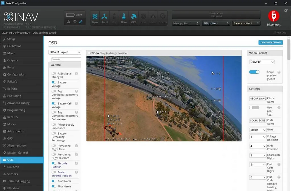
After re-entering the UI, go to the "OSD" tab. You can add elements to show what you want on your goggle screen under "General". You can also drag the elements to reposition to your liking.
Please make sure to save the changes on the bottom right of the UI.
Tip: It might be best to power on the XplorerHD and look through the goggles to make sure your elements are in the spots you want. It should update live-time as you make your changes.
Manual Gimbal Control (PWM)
Note: We haven't tried this ourselves but theoretically it should work. (Again, the Flight Controller and UI are NOT our products)
Certain "Wing" FC's have servo pads which you can switch your mode for camera control.

Our XplorerHD has built-in headtracking which uses "PTZ" mode to work as intended. However, you can choose to use "PPM" mode if you want manual gimbal control. (You will lose head tracking if you select PPM mode as it will not process the movement of the goggles to move the gimbal)

For our example, the FC has "S" pads number 1-9. As our gimbal is 3-axis, we will only need 3 wires to connect to the S pads on the FC.
To configure, the UI (example iNav) will have a servo tab as you can set your endpoints points and assign them to a switch on your radio transmitter.


Comments